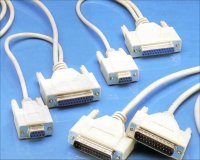
 When discussing serial connections for computers you are normally referring to the RS232 interface. Leads Direct sells a wide range of RS232 compatible serial leads and cables in both 9 and 25 pin configurations, including straight through and Null Modem leads as well as USB and Firewire which are also types of serial connection.
You can view and purchase these leads by visiting our Serial Leads which has literally thousands of products each with two sizes of image.
The RS232 serial port passes data in serial format (1 bit at a time over one line). This port supports a variety of devices, including a serial mouse, serial printer or modem that requires serial data transmission. Possibly the most common serial port is a 9 pin D shape.
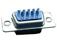
Connections to these connectors are most commonly made by soldering the cables to the ‘solder bucket’ terminals at the rear of the connector. Note that the same connector is often used both for chassis mounting and for cable mounting, in the latter case with the addition of a plastic or metal hood.
Solder tags at the rear of a DB9 serial connector
Modern computers ship with both Com1 and Com2 in this style, usually assembled to the motherboard as part of the ATX format.
Older machines use a 25 pin D shaped connector for Com2, the secondary serial port.
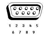
The pins are numbered left to right across the first row, and then the same on the second row, as per the diagram below:
The pin numbers are usually stamped into the moulding at the rear of the connector making the selection of the correct pins quite an easy task.
Standard 9 Pin RS232 Serial Wiring
| Pin | Signal | I/O | Definition |
| 1 | DCD | I | Data carrier detect |
| 2 | RXDA | I | Receive data |
| 3 | TXDA | O | Transmit data |
| 4 | DTR | O | Data terminal ready |
| 5 | GND | N/A | Signal ground |
| 6 | DSR | I | Data set ready |
| 7 | RTS | O | Request to send |
| 8 | CTS | I | Clear to send |
| 9 | RI | I | Ring indicator |
| Shell | N/A | N/A | Frame ground |
Standard 9 Pin RS232 Null Modem Wiring
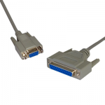
Null Modem leads and cables are used to connect two serial interfaces together, typically for data transfer using two female connectors.
These are also used for interfaces between computers and other products such as barcode scanners and till control in EPOS systems, below is the standard Null Modem pinout as used in our products. Leads Direct can offer a wide range of ready made Null Modem cables as well as custom ones made to your specifications.
| Pin | Pin |
| 1 | n/c |
| 2 | 3 |
| 3 | 2 |
| 4 | 6 |
| 5 | 5 |
| 6 | 4 |
| 7 | 8 |
| 8 | 7 |
| 9 | n/c |
| Shell | Shell or n/c |
Standard 25 Pin RS232 Serial Wiring
| Pin | Signal | I/O | Description |
|---|---|---|---|
|
1
|
GND | N/A | Shield Ground |
|
2
|
TXD |
O
|
Transmit Data |
|
3
|
RXD |
I
|
Receive Data |
|
4
|
RTS |
O
|
Request to Send |
|
5
|
CTS |
I
|
Clear to Send |
|
6
|
DSR |
I
|
Data Set Ready |
|
7
|
GND | N/A | System Ground |
|
8
|
CD |
I
|
Carrier Detect |
|
9
|
– |
N/A
|
RESERVED |
|
10
|
– |
N/A
|
RESERVED |
|
11
|
STF |
O
|
Select Transmit Channel |
|
12
|
S.CD |
I
|
Secondary Carrier Detect |
|
13
|
S.CTS |
I
|
Secondary Clear to Send |
|
14
|
S.TXD |
O
|
Secondary Transmit Data |
|
15
|
TCK |
I
|
Transmission Signal Element Timing |
|
16
|
S.RXD |
I
|
Secondary Receive Data |
|
17
|
RCK |
I
|
Receiver Signal Element Timing |
|
18
|
LL |
O
|
Local Loop Control |
|
19
|
S.RTS |
O
|
Secondary Request to Send |
|
20
|
DTR |
O
|
Data Terminal Ready |
|
21
|
RL |
O
|
Remote Loop Control |
|
22
|
RI |
I
|
Ring Indicator |
|
23
|
DSR |
O
|
Data Signal Rate Selector |
|
24
|
XCK |
O
|
Transmit Signal Element Timing |
|
25
|
TI |
I
|
Test Indicator |


